Control for servo control
The servo control (Code VE015-008) is an electronic module designed to easily and effectively manage one or more servomotors, both analog and digital.
Thanks to its versatility, it allows you to control two servos in parallel and, when necessary, a third servo with counter-phase movement. The control mode (button or switch) can be selected directly via a soldering pad on the board, offering maximum flexibility of use.
This system is ideal for applications in home automation, robotics, model making, automotive and in all those projects where precise and adjustable control of the movement of multiple servomotors is required.

TECHNICAL DATA
Supply voltage: 4 – 7 Vdc
Maximum current supported: 2A for previous periods
Adjustments:
Travel speed (single-turn linear trimmer)
Opening angle (single-turn linear trimmer)
Connections:
6-pin connector: two servos in parallel
3-pin connector: push-pull servo
2-pin terminal block: push button or switch
Operating mode: selectable via jumper SJ1 (closed = button, open = switch)

MAIN FEATURES
Simultaneous control of two servos in parallel and, optionally, of a third in push-pull.
Compatibility with analog and digital servo motors.
Quick selection between push button or switch operation.
Intuitive adjustments of opening angle and movement speed via dedicated trimmers.
Operation based on Microchip PIC12F1571 8-bit microcontroller for maximum reliability.
USE OF THE CIRCUIT
The integrated microcontroller manages the input state (button/switch) in real time, acquires the settings from the trimmers and generates a precise PWM signal for controlling servomotors.
Opening angle adjustment: using the “ANGLE” trimmer.
Rotating to the left → increasing the angle.
Rotating to the right → decrease the angle.
Speed regulation: via the “SPEED” trimmer.
Rotating to the right → slower movement.
Rotating to the left → faster movement.

"COUNTER-PHASE" SYSTEM
When a third servo is connected in counterphase, the module automatically manages opposite movements:
-
When switched on, SERVO1 (parallel) moves to 0° while SERVO2 (counterphase) positions itself at 180°.
-
During movement, the angles are complementary.
-
Example: angle set to 40° → SERVO1 = 40°, SERVO2 = 140°.
-
Example: angle set to 170° → SERVO1 = 170°, SERVO2 = 10°.
-
REGULATION PROCEDURE
-
Set the ANGLE and SPEED trimmers to the center of their travel.
-
Connect servos, button/switch and power supply correctly.
-
Power up the circuit: the servos automatically return to rest.
-
Press the button or flip the switch to start the movement.
-
Adjust the trimmers until you get the desired angle and speed.
APPLICATION FIELDS
-
Home automation (automated doors, windows, curtains, locking systems)
-
Automotive (flap management, custom actuators, opening systems)
-
Robotics (synchronized movements, robotic limbs, grasping systems)
-
Model making (planes, boats, radio-controlled vehicles)
VIDEO
AVAILABLE VARIANTS
Continuous movement
The servo rotates continuously back and forth as long as the button or switch is pressed/closed.
Angle and rotation speed adjustable via trimmer.
Continuous movement with central rest position
The servo starts from the central position (0°) and performs a continuous movement in both directions (±90° max).
Angle and rotation speed adjustable via trimmer.
Two-button navigation
Traditional movement, but with a second button dedicated to returning to the rest position.
Angle and rotation speed adjustable via trimmer.
Note: Only buttons (no switches) can be used. The push-pull servo output is not available, as its input is occupied by the second button.
Right/Left shift with two buttons and central rest position
The servo starts from the central position and moves to the right or left (max 90°) depending on the button pressed.
Angle and speed adjustable via trimmer.
Note: Only buttons can be used (no switches). Push-pull servo output is not available.
Two-button navigation with two distinct corners
Two buttons, each associated with a different movement angle.
Each angle is adjustable via trimmer.
Note: Buttons only (no switches). No push-pull servo output. Running speed fixed at maximum, as the speed trimmer is dedicated to the angle of the second movement.
One-button movement and two distinct angles in succession
With a single button, the servo performs two consecutive movements at different angles.
Each angle is adjustable via trimmer.
Note: Buttons only (no switches). Speed fixed at maximum, for the same reason as in the previous mode.
Below is a video of the available variants:
RELATED PRODUCTS

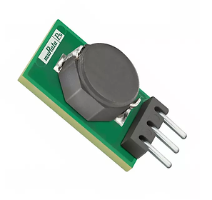
Switching power supply with 5vdc 1.5A output.
Ideal for powering the servo control circuit with voltages between 7 and 36Vdc

